
Imagine the thrill of a powerful electric bike whizzing through the streets, or the quiet hum of a drone soaring through the sky. These feats of modern engineering wouldn’t be possible without the heart of the system: the 48v brushless motor controller. But for many, the intricate wiring diagram that accompanies these controllers can be daunting, a labyrinth of wires and connections that seem to defy logic. Fear not, intrepid explorer of electric motion! This article will serve as your compass through this complex world, guiding you toward a clear understanding of the 48v brushless motor controller wiring diagram.

Image: www.vrogue.co
Navigating the 48v brushless motor controller wiring diagram is crucial for anyone seeking to build, repair, or customize electric vehicles, robots, or other motorized systems. This diagram provides a blueprint for the connections between the controller, the battery, the motor, and various sensors. Understanding this diagram empowers you to troubleshoot issues, optimize performance, and even reconfigure your setup to meet your specific needs.
Unraveling the Mysteries: A Deep Dive into the 48v Brushless Motor Controller Wiring Diagram
Before we embark on our wiring adventure, let’s establish a solid foundation. A brushless motor controller, also known as an electronic speed controller (ESC), serves as the brain of an electric motor system. It receives instructions from a user (either directly via a throttle or indirectly via a microcontroller), converts DC power from the battery into alternating current (AC), and sends the precise amount of power to the brushless motor to achieve desired speeds and torque.
The 48v brushless motor controller wiring diagram typically consists of the following key components:
1. Power Input
- Battery Connections: The diagram clearly indicates how to connect the positive (+) and negative (-) terminals of the battery to the controller. This provides the controller with the necessary energy to power the motor.
- Battery Safety Features: The diagram might also display the connections for safety features like undervoltage protection (protects the battery from being drained too low) and overcurrent protection (prevents excessive current flow that can damage the battery or controller).
2. Motor Connections
- Phase Wires: Brushless motors employ three winding phases (typically labeled U, V, and W or A, B, and C). The diagram shows how these phase wires from the motor connect to the controller.
- Hall Sensor Wires: Many brushless motors incorporate Hall sensors to provide feedback on the motor’s position. Hall sensor wires connect to the controller, enabling precise control of the motor’s rotation.
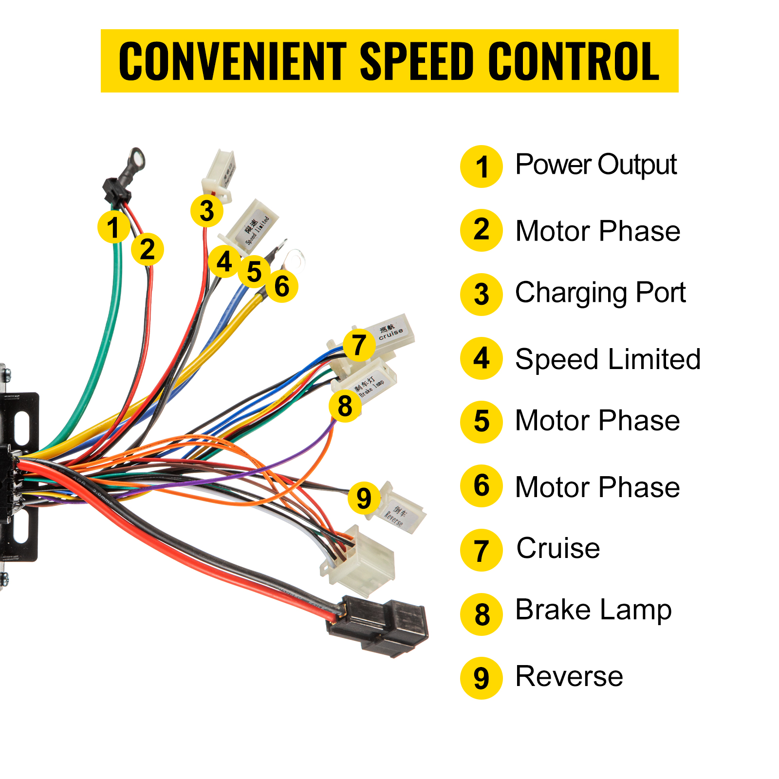
Image: www.vevor.ca
3. Control and Communication
- Throttle Signal: The throttle is a key input for controlling motor speed. The diagram demonstrates how the throttle signal wire connects to the controller, allowing the user to adjust the motor’s speed.
- Auxiliary Connections: Depending on the controller’s features, the diagram may also show connections for auxiliary components like:
- Brake/Reverse Signal: Allows for stopping or reversing the motor.
- Temperature Sensor: Monitors the motor and controller temperature, enhancing safety and performance.
- Current Sensor: Measures the current flow through the motor for diagnostics and control.
- CAN Bus: Enables communication with other devices in a larger system.
4. Safety Precautions
- Fuse: A fuse is a critical safety component that protects the wiring and components from overcurrents. The diagram will indicate where to install a fuse in the power input circuit.
- Grounding: The importance of grounding cannot be overstated. Proper grounding ensures safe electrical operation and prevents shocks. The diagram will clearly illustrate how to connect the ground wire to the system.
Understanding the Code
- Signal Types: The diagram might employ color-coding or symbols to designate different types of signals (e.g., power, control, ground, sensor).
- Labels and Diagrams: Look for labels clearly indicating the purpose and function of each wire and connection point.
- Connector Compatibility: Pay attention to the types of connectors used (e.g., bullet connectors, XT60, banana plugs) and ensure compatibility with your components.
Beyond the Diagram: Expert Insights and Actionable Tips
While the wiring diagram is a crucial map, it’s essential to consider additional insights from experienced builders and technicians:
- Patience and Caution: Working with electrical systems requires care and attention. Always disconnect power before working on any wiring and double-check your connections before applying power.
- Test and Debug: After connecting everything, start with a gradual power increase and monitor the system carefully for any unusual behavior.
- Document Your Work: Keep track of your wiring progress with photos, diagrams, or detailed notes. This will help you troubleshoot issues or revert to a previous configuration if needed.
48v Brushless Motor Controller Wiring Diagram
Charting Your Course to Electric Motion
Mastering the 48v brushless motor controller wiring diagram unlocks a world of possibilities for anyone interested in electric vehicles, robots, and other creative projects. Remember, this diagram is not just a collection of wires and connections; it’s a roadmap to innovation, empowering you to harness the power of electricity and bring your motorized ideas to life. But remember, your journey into the world of electric motion begins with understanding the language of this diagram. So, dive in, explore, and let the 48v brushless motor controller wiring diagram guide you to exciting new horizons.


